The VCR connector, as an indispensable precision connection component in vacuum and high-purity fluid systems, its installation quality directly affects the system's sealing performance, stability and service life. Based on industry authoritative technical specifications and engineering practical experience, this article systematically sorts out the installation process, technical key points and quality control methods of the VCR connector, providing a standardized operation guide for engineering technicians in fields such as semiconductors, biopharmaceuticals, and high-energy physics.
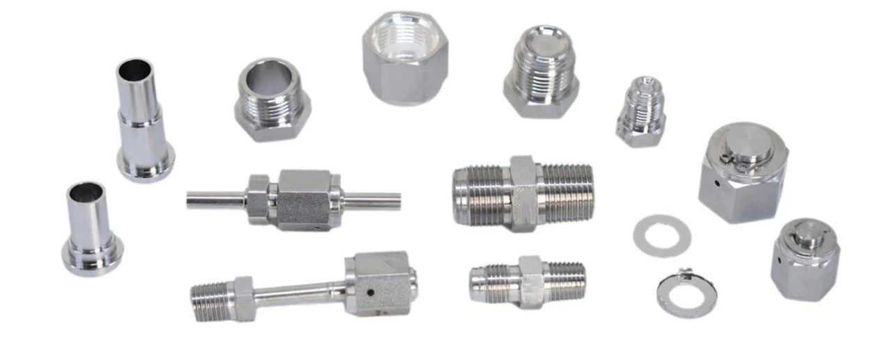
I. Technical Characteristics and Working Principle of VCR Connector
The VCR joint (Vacuum Coupling Radius Seal) employs a metal gasket face sealing technology. Through the interlocking mechanism of internal and external threads, it presses the metal gasket to undergo plastic deformation, forming a leak-free metal-to-metal seal. Its core advantages are as follows:
1. Excellent sealing performance: It can achieve zero leakage within the range of vacuum to high pressure, with a leakage rate lower than 1×10⁻¹¹ Pa·m³/s
2. Wide temperature range: The working temperature covers -200℃ to 600℃, suitable for extreme conditions.
3. Reusable and detachable: Utilizing a replaceable metal gasket design, it enables multiple disassemblies without compromising the sealing performance.
4. High cleanliness: The components undergo electro-polishing and cleaning processes, with a surface roughness of Ra ≤ 0.2 μm, meeting the CLASS 1 cleanliness requirements of the semiconductor industry.
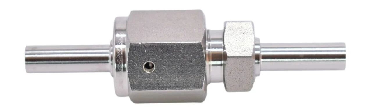
II. Pre-installation Preparation and Component Identification
2.1 Component Integrity Inspection Standards:
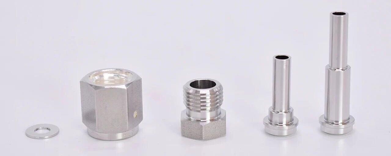
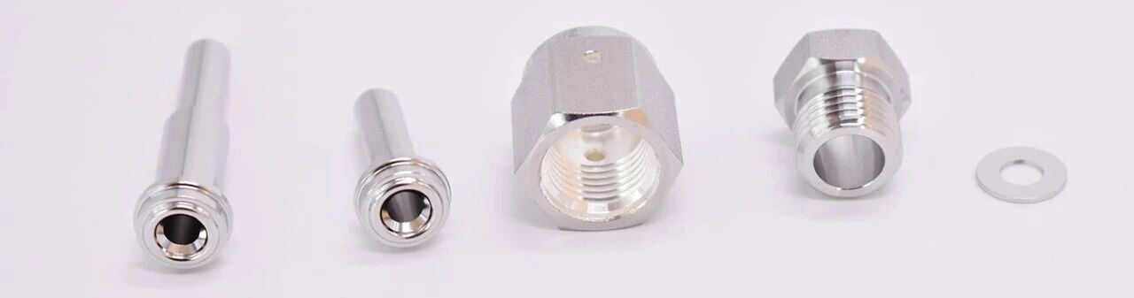
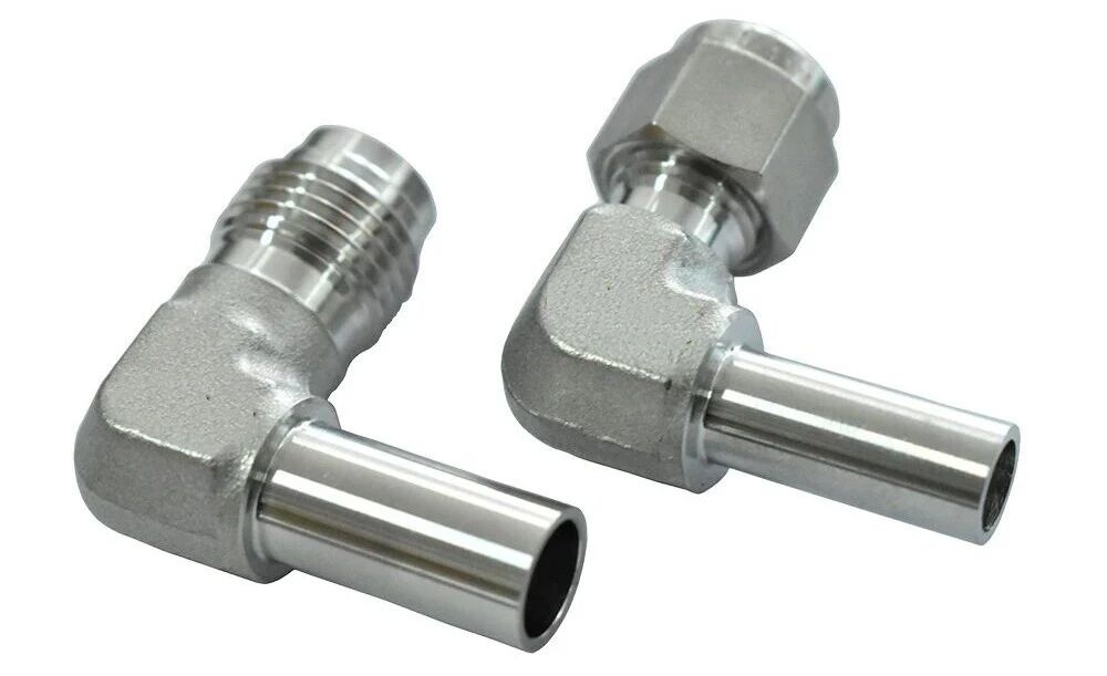
The VCR connector component includes: connector body (Gland): divided into long type (Long Tube) and short type (Short Tube);
internal and external threaded nuts (Male/Female Nut): need to distinguish between metric (e.g. 8mm) and imperial (e.g. 1/4") specifications;
metal gaskets (Gasket): divided into claw-type (Retained) and non-claw-type (Nonretained); materials include 316L stainless steel, nickel-based alloys (such as C-276), copper alloys, etc.; the matching of pipe diameter, wall thickness and material must be confirmed.
2.2 Tools and Environmental Preparation:
Special tools: Double-ended fixed wrench (the opening size should match the hexagonal head of the nut), torque limiting wrench (accuracy ±3%)
inspection equipment: Vacuum helium mass spectrometry leak detector (sensitivity ≥ 1×10⁻¹² Pa·m³/s), pressure testing pump (0-10MPa)
environmental requirements: Cleanliness above CLASS 10000, temperature 15-25℃, humidity ≤ 60%, personal protection: Dust-free full-body suit, nitrile gloves, goggles
III. Standardized Installation Procedure
3.1
Pipeline pre-treatment cutting and flange: Use a dedicated pipe cutting machine for cold cutting to ensure the end face perpendicularity ≤ 0.5°, without burrs,
oxidation layer stress relief treatment: Perform annealing treatment within a 100mm range of the welding area to eliminate mechanical processing stress.
Cleaning verification: Use trichloroethylene ultrasonic cleaning (frequency 40kHz, time 15min), followed by blowing and drying with high-purity nitrogen gas (9N grade).
3.2
Component assembly: Pre-install the external thread nut onto the pipe end to be welded, ensuring the starting end of the thread is ≥ 5mm away from the pipe end.
Welding process: Automatic track welding (recommended): Use pulsed TIG welding, with argon purity ≥ 99.999%, back protection gas flow rate 8-10L/min.
Key parameters: Current 80-120A, welding speed 150-200mm/min, interlayer temperature ≤ 150℃.
Gasket installation: With claw gasket: Insert into the sealing groove of the joint body to ensure the claws are fully embedded. Without claw gasket: Place flatly onto the sealing surface of the internal thread nut, avoiding tilting or folding.
3.3
Alignment and locking initial positioning: Manually screw the external and internal thread nuts together until they contact each other.
Record the initial angle and torque control: Stainless steel/nickel-based gasket: Final locking torque 15-20N·m (corresponding to rotation 1/8 circle).
Copper alloy gasket: Final locking torque 10-15N·m (corresponding to rotation 1/4 circle). Mark verification: Use a dust-free marker pen to draw a continuous straight line on the hexagonal head of the nut to ensure the rotation angle complies with the specification.
IV. Key Points for Installation Quality Control
4.1
Visual inspection of process: Confirm that the gasket is not offset, the screw thread is undamaged, and the welding joint has no air holes or crack marks.
Verification: Use a protractor to measure the rotation angle, with an allowable deviation of ±5°.
Leakage test:
Positive pressure test: 5 bar helium gas, maintain pressure for 30 minutes, and the pressure drop should be ≤ 0.5%.
Vacuum test: Suction to 1×10⁻⁶ Pa, and the reading of the helium mass spectrometer should be ≤ 1×10⁻¹⁰ Pa·m³/s.
4.2
Analysis of Common Defects
1.Defect Type : Gasket leakage
The root cause : Insufficient installation angle / Gasket damage
Solution : Reinstall and replace the gasket
2.Defect Type : Thread locking
The root cause : Welding thermal influence / Insufficient lubrication
Solution : Cool for 24 hours after welding, use MoS₂ lubricant
3. Defect Type : Welding cracks
The root cause : Excessive interlayer temperature / Inadequate purity of shielding gas
Solution : Strictly control welding parameters, use 5N grade argon gas
V. Installation Specifications for Special Conditions
5.1 For high-temperature systems (>400℃), nickel-based alloy gaskets (such as Inconel 625) are selected. Graphite wrapped gaskets are used as auxiliary seals. After welding, a solution treatment (holding at 1050℃ for 1 hour, water quenching) is performed.
5.2 In a vibration environment, anti-loosening devices (such as double nuts, spring washers) are installed. Flexible pipe sections are used to isolate the vibration source. Regular torque rechecks are conducted (every 3 months).
5.3 For the biopharmaceutical system, the ASME BPE standard is implemented for surface treatment. Electrolytic polishing process (surface roughness Ra ≤ 0.08 μm) is used. After installation, online cleaning and sterilization by CIP/SIP are carried out.
VI. Maintenance and Reuse Guidelines
New gaskets must be replaced each time they are disassembled and installed. Reuse of threads is prohibited. Thread repair: Use thread repair kits (such as Helicoil) to handle worn threads. Storage requirements: Components should be stored in a dry nitrogen environment with a relative humidity of ≤ 30%. Life assessment: It is recommended to conduct metallographic testing every 5 years to assess the intergranular corrosion degree.
VII. Industry Application Cases
In the construction of a 12-inch wafer factory, a special gas delivery system constructed using VCR joints achieved: Leakage rate: < 1×10⁻⁹ Pa·m³/s Installation efficiency: Installation time for a single joint ≤ 8 minutes Maintenance cost: Reduced by 65% compared to traditional welding connections
Conclusion:
The precise installation of VCR joints is a key link in ensuring system reliability. By strictly following standardized procedures, implementing full-process quality control, and combining advanced detection technologies, connection quality can be significantly improved, and system lifespan can be extended. As semiconductor processes advance towards 3nm nodes, the installation accuracy requirements for VCR joints will continue to increase. Engineering technicians need to continuously optimize process parameters to promote the development of connection technology to a higher level.